


STM32 microcontroller minimum system full analysis
 31
31Global electronic component supplier AMPHEO PTY LTD: Rich inventory for one-stop shopping. Inquire easily, and receive fast, customized solutions and quotes.
A minimum system for an STM32 microcontroller (MCU) refers to the simplest hardware configuration required to make the MCU operational. This includes the essential components and connections needed for the MCU to power up, run code, and interact with external peripherals. Below is a detailed analysis of the STM32 minimum system:
1. STM32 Microcontroller
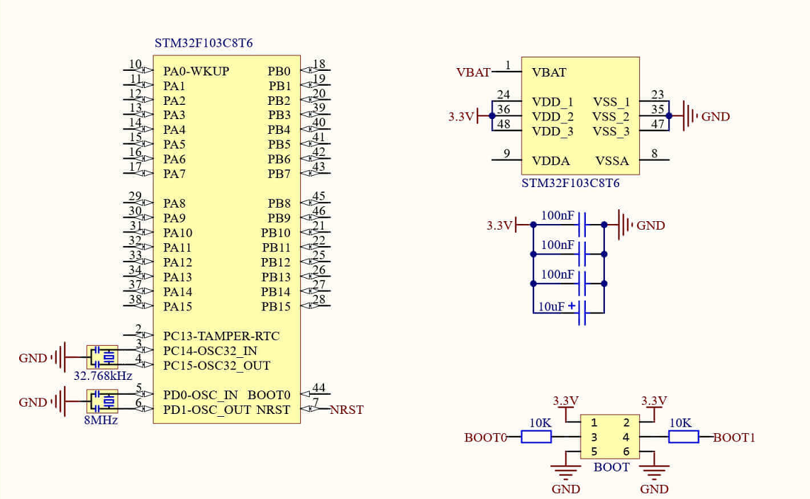
The STM32 MCU is the core of the system. STM32 microcontrollers are based on ARM Cortex-M cores (e.g., Cortex-M0, M3, M4, M7) and come in various families (e.g., STM32F0, STM32F1, STM32F4, STM32H7). The specific model determines the features, performance, and peripherals available.
2. Power Supply
The STM32 MCU requires a stable power supply to operate. Key considerations:
-
Voltage Range:
-
Most STM32 MCUs operate at 1.8V to 3.6V (check the datasheet for your specific model).
-
A 3.3V supply is commonly used.
-
-
Decoupling Capacitors:
-
Place 100nF ceramic capacitors close to each power pin (VDD/VSS) to filter noise.
-
Add a 4.7µF to 10µF bulk capacitor near the MCU for additional stability.
-
-
Power Pins:
-
Connect all VDD pins to the power supply.
-
Connect all VSS pins to the ground.
-
3. Clock Source
The STM32 requires a clock source for its operation. There are two options:
-
Internal Clock:
-
STM32 MCUs have internal RC oscillators (e.g., 8 MHz for HSI, 32 kHz for LSI).
-
Suitable for basic applications but less accurate.
-
-
External Clock:
-
Use an external crystal oscillator for higher accuracy.
-
High-Speed Crystal (HSE): Typically 4-26 MHz.
-
Low-Speed Crystal (LSE): Typically 32.768 kHz for RTC (Real-Time Clock).
-
-
Add load capacitors (e.g., 10-22 pF) to the crystal oscillator circuit.
-
4. Reset Circuit
A reset circuit ensures the MCU starts correctly:
-
Reset Pin (NRST):
-
Connect a 10kΩ pull-up resistor to VDD.
-
Add a 100nF capacitor to ground for debouncing.
-
Optionally, include a push-button for manual reset.
-
5. Boot Configuration
The STM32 has boot modes to determine how it starts:
-
Boot Pins (BOOT0 and BOOT1):
-
Set BOOT0 and BOOT1 to configure the boot mode:
-
BOOT0=0, BOOT1=X: Boot from Flash memory (default).
-
BOOT0=1, BOOT1=0: Boot from system memory (for firmware updates).
-
BOOT0=1, BOOT1=1: Boot from embedded SRAM.
-
-
Use pull-up/pull-down resistors to set the desired boot mode.
-
6. Debugging Interface
For programming and debugging:
-
SWD (Serial Wire Debug):
-
Use the SWDIO and SWCLK pins for programming and debugging.
-
Connect a 10kΩ pull-up resistor on SWDIO.
-
-
JTAG:
-
Optional alternative to SWD, but requires more pins.
-
7. GPIO Configuration
-
Unused Pins:
-
Leave unused GPIO pins unconnected or configure them as inputs with pull-up/down resistors to avoid floating states.
-
-
LEDs and Buttons:
-
Add LEDs and buttons for basic debugging and user interaction.
-
8. Optional Components
-
Voltage Regulator:
-
If the input voltage is higher than 3.3V, use a 3.3V regulator (e.g., LDO).
-
-
External Peripherals:
-
Add sensors, displays, or communication modules (e.g., UART, SPI, I2C) as needed.
-
Schematic Diagram of STM32 Minimum System
Here’s a simplified schematic representation:
-
Power Supply:
VDD ----||--- GND (100nF decoupling capacitors)
VDD ----||--- GND (4.7µF bulk capacitor)
-
Reset Circuit:
NRST ---- 10kΩ ---- VDD
NRST ---- 100nF ---- GND
NRST ---- Push Button ---- GND
-
Clock Circuit:
OSC_IN ---- Crystal ---- OSC_OUT
OSC_IN ---- 10-22pF ---- GND
OSC_OUT ---- 10-22pF ---- GND
-
Boot Configuration:
BOOT0 ---- 10kΩ ---- GND (for Flash boot mode)
BOOT1 ---- 10kΩ ---- GND
-
Debugging Interface:
SWDIO ---- 10kΩ ---- VDD
SWDIO ---- Debugger
SWCLK ---- Debugger
Example: STM32F103C8T6 Minimum System
-
MCU: STM32F103C8T6 (Cortex-M3, 64 KB Flash, 20 KB RAM).
-
Power Supply: 3.3V.
-
Clock: 8 MHz crystal (HSE).
-
Reset: 10kΩ pull-up resistor, 100nF capacitor, and push-button.
-
Boot Mode: BOOT0=0, BOOT1=0 (Flash memory).
-
Debugging: SWD interface.
Conclusion
A minimum system for an STM32 microcontroller includes:
-
Power supply with decoupling capacitors.
-
Clock source (internal or external).
-
Reset circuit.
-
Boot configuration.
-
Debugging interface (SWD or JTAG).
This setup ensures the STM32 MCU can power up, execute code, and be programmed/debugged. Additional peripherals can be added based on the application requirements.