How to use Arduino to construct simple control circuits?
Global electronic component supplier AMPHEO PTY LTD: Rich inventory for one-stop shopping. Inquire easily, and receive fast, customized solutions and quotes.
Using Arduino to construct simple control circuits is an excellent way to learn about electronics, automation, and programming. Arduino makes it easy to interface with components like LEDs, motors, sensors, and switches to control them using simple control logic. Below are a few examples of basic control circuits that can be built with Arduino, using digital and analog I/O pins.

1. Controlling an LED (Simple On/Off Control)
Components Needed:
- Arduino board (e.g., Uno, Nano)
- LED
- 220Ω resistor
- Breadboard
- Jumper wires
Circuit:
- Connect the anode (long leg) of the LED to digital pin 13 on the Arduino.
- Connect the cathode (short leg) of the LED to one side of the 220Ω resistor.
- Connect the other side of the resistor to GND on the Arduino.
Code Example:
This circuit will blink the LED on and off every second. The Arduino controls the LED by setting the output pin to HIGH (turning it on) and LOW (turning it off).
2. Controlling an LED with a Pushbutton (Simple Switch Control)
Components Needed:
- Arduino board
- LED
- Pushbutton
- 220Ω resistor (for the LED)
- 10kΩ resistor (for the pull-down resistor)
- Breadboard
- Jumper wires
Circuit:
- Connect the anode of the LED to digital pin 13.
- Connect the cathode of the LED to GND via a 220Ω resistor.
- Connect one side of the pushbutton to digital pin 2 and the other side to GND.
- Use a 10kΩ pull-down resistor between pin 2 and GND to ensure the button's state is LOW when not pressed.
Code Example:
In this circuit, pressing the button turns the LED on, and releasing the button turns it off. The button’s state is checked continuously, and based on whether it's pressed or not, the LED is controlled.
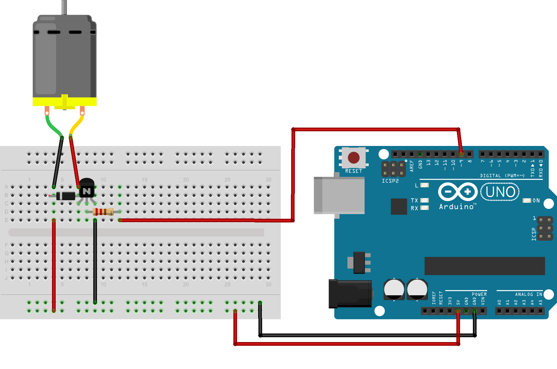
3. Controlling a DC Motor with a Pushbutton (Simple Motor Control)
Components Needed:
- Arduino board
- DC motor
- Pushbutton
- Motor driver (e.g., L298N or L293D)
- External power supply for motor
- Diode (e.g., 1N4007) for back EMF protection
- Resistor for the button
- Breadboard and jumper wires
Circuit:
- Connect the motor driver input pins (e.g., IN1, IN2 on L298N) to digital pins 3 and 4 on the Arduino.
- Connect the motor terminals to the output pins of the motor driver.
- Connect the pushbutton to digital pin 2.
- Provide external power to the motor driver, and connect the ground to GND on the Arduino.
Code Example:
This circuit turns the DC motor on when the button is pressed and stops it when released. The motor’s direction can be controlled by setting motorPin1 and motorPin2 accordingly.
4. PWM Control of LED Brightness (Analog Control)
Components Needed:
- Arduino board
- LED
- 220Ω resistor
- Breadboard
- Jumper wires
Circuit:
- Connect the anode of the LED to digital pin 9 (a PWM-enabled pin).
- Connect the cathode of the LED to GND via a 220Ω resistor.
Code Example:
This circuit uses PWM (Pulse Width Modulation) to control the brightness of the LED, gradually increasing and decreasing the brightness in a loop.
5. Simple Temperature-based Fan Control (Using a Temperature Sensor)
Components Needed:
- Arduino board
- Temperature sensor (e.g., LM35)
- DC fan
- Relay module (for switching the fan)
- Breadboard and jumper wires
Circuit:
- Connect the LM35 temperature sensor to analog pin A0.
- Connect the fan to the relay module and use digital pin 7 to control the relay.
- Provide power to the fan through the relay module, ensuring proper voltage and current ratings.
Code Example:
In this setup, the fan turns on if the temperature exceeds 25°C, and turns off when the temperature is below that threshold.
Conclusion
By combining Arduino's I/O capabilities with external components, you can create a wide variety of control circuits for different applications. These projects will teach you how to interact with the physical world using digital and analog signals, pulse-width modulation, and even more advanced control like temperature-based systems. As you get more comfortable with the basics, you can explore more complex circuits and projects to extend your skills.
