


Design and Implementation of a Smart Home System Based on STM32
 13
13Global electronic component supplier AMPHEO PTY LTD: Rich inventory for one-stop shopping. Inquire easily, and receive fast, customized solutions and quotes.
1. Overview
A Smart Home System using STM32 microcontrollers enables automation and remote control of home appliances, security, lighting, and environmental monitoring. This project integrates sensors, wireless communication, and a user interface for centralized control.
2. System Architecture
The system consists of:
-
STM32 Microcontroller (e.g., STM32F103C8T6 or STM32F407VG)
-
Sensors (Temperature, Humidity, Motion, Gas, Light)
-
Actuators (Relays, Servo Motors, LEDs)
-
Wireless Communication (Wi-Fi, Bluetooth, Zigbee, or LoRa)
-
User Interface (Mobile App, Web Dashboard, or Touchscreen LCD)
Block Diagram
+-------------------+       +-------------------+       +-------------------+
|                   |       |                   |       |                   |
|   STM32 MCU       |<----->|   Sensors         |<----->|   Actuators       |
|   (Main Control)  |       |   (Temp, Motion)  |       |   (Relays, LEDs)  |
+-------------------+       +-------------------+       +-------------------+
        ^                                                      ^
        |                                                      |
        v                                                      v
+-------------------+                               +-------------------+
|   Wireless Module |                               |   User Interface  |
|  (Wi-Fi/Bluetooth)|                               |   (Mobile/Web)    |
+-------------------+                               +-------------------+
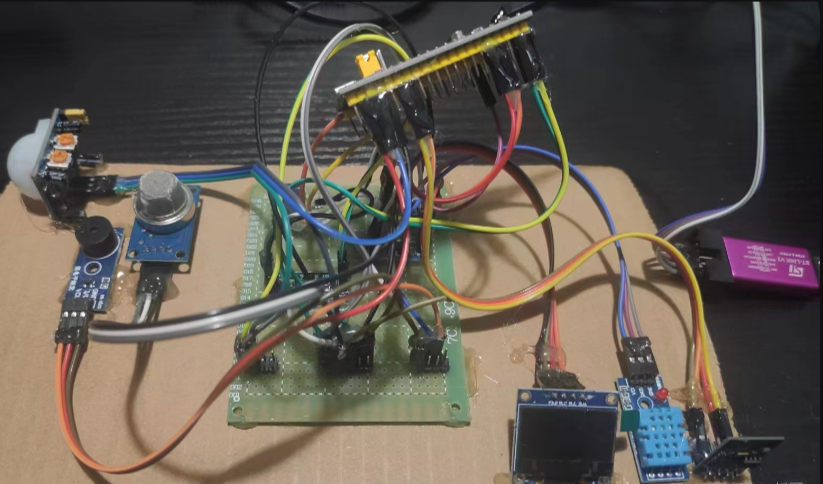
3. Hardware Components
3.1 STM32 Microcontroller
-
STM32F103C8T6 (Blue Pill, cost-effective) or STM32F407VG (more powerful)
-
Features:
-
Multiple GPIOs for sensors and actuators
-
ADC for analog sensors (temperature, gas)
-
PWM for motor/servo control
-
UART/I2C/SPI for communication
-
3.2 Sensors
| Sensor | Function | Interface |
|---|---|---|
| DHT11/DHT22 | Temperature & Humidity | Digital |
| PIR Sensor | Motion Detection | Digital |
| MQ-2/MQ-135 | Gas/Smoke Detection | Analog |
| LDR | Light Intensity Detection | Analog |
| Ultrasonic | Distance Measurement (Security) | Digital |
3.3 Actuators
| Actuator | Function | Control Method |
|---|---|---|
| Relay Module | Control Appliances (AC/DC) | GPIO (High/Low) |
| Servo Motor | Door Lock Control | PWM |
| LED Strip | Smart Lighting | PWM |
3.4 Wireless Communication
-
Wi-Fi (ESP8266/ESP32) – Connects to cloud (Blynk, MQTT)
-
Bluetooth (HC-05/HC-06) – Local smartphone control
-
Zigbee (XBee) – Low-power mesh networking
-
LoRa (RA-02) – Long-range IoT applications
3.5 Power Supply
-
5V/3.3V Regulator (LM7805/AMS1117)
-
Battery Backup (18650 Li-ion + TP4056 Charger)
4. Software Implementation
4.1 Firmware Development (STM32CubeIDE)
-
STM32 HAL Library for peripheral configuration
-
FreeRTOS (optional, for multitasking)
-
Communication Protocols:
-
UART (for Bluetooth/Wi-Fi modules)
-
I2C/SPI (for sensors like BMP280)
-
MQTT/HTTP (for cloud connectivity)
-
4.2 Key Functions
1. Sensor Data Acquisition
// Read Temperature & Humidity (DHT11)
void DHT11_Read(float *temp, float *humidity) {
    // Send start signal
    HAL_GPIO_WritePin(DHT11_GPIO_Port, DHT11_Pin, GPIO_PIN_RESET);
    HAL_Delay(18);
    HAL_GPIO_WritePin(DHT11_GPIO_Port, DHT11_Pin, GPIO_PIN_SET);

    // Read 40-bit data
    uint8_t data[5];
    for (int i = 0; i < 5; i++) {
        data[i] = DHT11_ReadByte();
    }

    *humidity = data[0];
    *temp = data[2];
}
2. Relay Control (Appliance Switching)
void Control_Relay(uint8_t relay_num, uint8_t state) {
    switch(relay_num) {
        case 1: HAL_GPIO_WritePin(RELAY1_GPIO_Port, RELAY1_Pin, state); break;
        case 2: HAL_GPIO_WritePin(RELAY2_GPIO_Port, RELAY2_Pin, state); break;
    }
}
3. Wireless Communication (Wi-Fi + MQTT)
// Send sensor data to MQTT broker (via ESP8266)
void MQTT_Publish(char *topic, char *payload) {
    char cmd[100];
    sprintf(cmd, "AT+MQTTPUB=0,\"%s\",\"%s\",0,0\r\n", topic, payload);
    HAL_UART_Transmit(&huart1, (uint8_t*)cmd, strlen(cmd), HAL_MAX_DELAY);
}
5. User Interface Options
5.1 Mobile App (Blynk/Home Assistant)
-
Blynk (Drag-and-drop IoT dashboard)
-
Home Assistant (Open-source home automation)
-
Custom Android/iOS App (MIT App Inventor, Flutter)
5.2 Web Dashboard (Node.js + MQTT)
-
MQTT Broker (Mosquitto)
-
Node-RED (Flow-based programming)
-
React.js Dashboard (Real-time monitoring)
5.3 Local Touchscreen (Nextion LCD)
-
Nextion HMI for interactive control
-
STM32 UART Communication to update display
6. System Workflow
-
Sensors collect data (temperature, motion, gas)
-
STM32 processes data and makes decisions (e.g., turn on fan if hot)
-
Wireless module sends alerts to phone/cloud
-
User controls devices via app/voice (Google Assistant/Alexa)
-
Actuators execute commands (relay turns on light)
7. Enhancements
-
Voice Control (Google Assistant/Alexa integration)
-
AI-Based Automation (predictive heating/cooling)
-
Solar Power Integration (for energy efficiency)
-
Facial Recognition Door Lock (OpenCV + STM32)
8. Conclusion
This STM32-based Smart Home System provides:
✅ Remote monitoring & control
✅ Energy efficiency
✅ Security enhancements
✅ Scalability (supports more sensors/actuators)