


What is A Solid State Relay (SSR) ?
September 13 2023  1636
1636
1636Inquiry
Global electronic component supplier AMPHEO PTY LTD: Rich inventory for one-stop shopping. Inquire easily, and receive fast, customized solutions and quotes.
QUICK RFQ
ADD TO RFQ LIST
This blog is all about solid-state relays (SSRs). We will be delving into the basics of SSRs, their working principles, and their benefits when compared to mechanical relays.
What is A Solid State Relay?
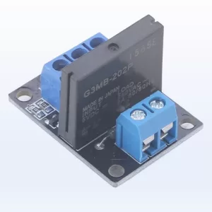
A solid-state relay (SSR) is a relay and an electronic switching device that uses semiconductor components, such as transistors and optocouplers, to switch electrical loads. Unlike traditional electromechanical relays that use mechanical contacts to make or break connections, solid-state relays rely on electronic components for their operation. Here are some key features and characteristics of solid-state relays: Solid-State Components: SSRs use semiconductor devices, such as thyristors (SCRs), triacs, or power MOSFETs, to control the flow of current. These components provide fast and reliable switching without any moving parts. Optocouplers: Many SSRs incorporate optocouplers or optoisolators, which use a combination of an LED and a phototransistor or photodiode to provide electrical isolation between the control input and the load output. This isolation protects the control circuitry from voltage spikes, noise, and potential hazards. Input Control: SSRs are typically controlled by low-power signals, such as digital or analog control signals, which activate the internal semiconductor devices. The control input can be a DC voltage, AC voltage, or even a digital signal, depending on the specific SSR design. Load Switching: Solid-state relays are capable of switching both AC and DC loads. AC SSRs are commonly used for switching AC loads, while DC SSRs are used for DC loads. The load current and voltage ratings vary depending on the specific SSR model. Zero-Crossing Switching: Some SSRs feature zero-crossing switching, where the relay activates the load circuit at the zero-crossing point of the AC waveform. This reduces electrical stress on the load and minimizes electrical noise generated during switching. Applications: Solid-state relays are used in various applications, including industrial automation, process control systems, motor control, lighting control, robotics, HVAC systems, medical equipment, and more. They are particularly useful in situations where fast, reliable, and noise-free switching is required.3 types of Solid State Relays
There are three common types of solid-state relays (SSRs) based on the type of semiconductor switching device they use: SSRs with Thyristors (SCRs) Thyristor-based SSRs use Silicon-Controlled Rectifiers (SCRs) as the switching device. SCRs are four-layer semiconductor devices that can handle high voltages and currents. Once triggered, an SCR remains conducting until the current falls below a certain threshold. Thyristor-based SSRs are commonly used for high-power AC loads.SSRs with Triacs
Triac-based SSRs use Triacs as the switching device. Triacs are bidirectional semiconductor devices capable of switching both halves of an AC waveform. They can control AC loads by turning on and off at the zero-crossing point of the AC waveform. Triac-based SSRs are widely used for AC loads in applications such as lighting control, heating systems, and motor control. SSRs with Power MOSFETs SSRs based on Power Metal-Oxide-Semiconductor Field-Effect Transistors (MOSFETs) use MOSFETs as the switching device. Power MOSFETs are voltage-controlled devices that offer low on-resistance and fast switching speeds. They are commonly used for both AC and DC loads, offering efficient and reliable switching. MOSFET-based SSRs are suitable for a wide range of applications, including industrial automation, robotics, and power electronics.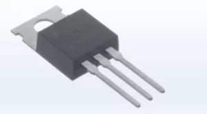
How does A Solid State Relay Work?
A solid-state relay (SSR) works by using semiconductor devices to control the flow of current to the load. Here's a general explanation of how an SSR operates: Input Control: The control input of the SSR receives a low-power signal, typically a voltage or current, to activate the relay. This input signal can come from a microcontroller, PLC (Programmable Logic Controller), or other control devices. Optocoupler Isolation: Many SSRs incorporate an optocoupler or optoisolator, which provides electrical isolation between the control input and the load output. The optocoupler consists of an LED on the control side and a phototransistor or photodiode on the output side. When the control input signal activates the LED, it emits light, which then triggers the phototransistor or photodiode. Semiconductor Switching: The activated phototransistor or photodiode in the SSR receives the light from the optocoupler and controls the current flow through the semiconductor switchings devices, such as thyristors (SCRs), triacs, or power MOSFETs. The specific type of semiconductor device used depends on whether the SSR is designed for AC or DC switching. AC SSR Operation: In the case of an AC SSR, when the control input activates the SSR, the internal semiconductor device switches on and allows the AC current to flow through the SSR. The switching device turns off automatically when the AC current crosses zero, which is known as zero-crossing switching. This helps minimize electrical noise and reduces stress on the load. DC SSR Operation: For DC SSRs, the control input signal activates the semiconductor device, allowing the DC current to flow through the SSR. The device remains in the on state until the control input signal is deactivated or the power is removed. Load Control: The switched current from the SSR flows to the load, such as a motor, heater, or lamp. The load is connected to the load terminals of the SSR, and the SSR acts as a bridge between the control input and the load. Load Isolation: SSRs provide electrical isolation between the control circuit and the load circuit, protecting the control circuit from voltage spikes, noise, and potential hazards from the load side. Heat Dissipation: During operation, SSRs generate heat due to the current flowing through the semiconductor devices. To prevent overheating, SSRs often include built-in heat sinks or require external heat sinking to dissipate the heat effectively. By utilizing semiconductor devices and optocouplers, solid-state relays offer advantages such as faster switching speeds, enhanced reliability, reduced noise generation, and electrical isolation between the control and load circuits. However, it's important to consider the specific specifications and application requirements when selecting an SSR, as they can vary between different models and manufacturers.Solid State Relay vs. Mechanical
Solid-state relays (SSRs) and mechanical relays are two different types of relays with distinct operating principles and characteristics. Here's a comparison between the two:Operating Principle
SSR: Solid-state relays use semiconductor devices, such as thyristors, triacs, or power MOSFETs, to control the current flow. They do not have any moving parts and rely on electronic switching. Mechanical Relay: Mechanical relays use electromechanical switches with mechanical contacts that physically open and close to control the current flow.Switching Speed
SSR: Solid-state relays have fast switching speeds, typically in the range of microseconds to milliseconds. This allows for rapid response and high-frequency switching. Mechanical Relay: Mechanical relays have slower switching speeds compared to SSRs, typically in the range of milliseconds to seconds. The mechanical movement of the contacts introduces a delay in the switching process.Electrical Life
SSR: Solid-state relays have a longer electrical life compared to mechanical relays. Since SSRs do not have moving parts, there is no physical wear and tear on contacts, resulting in a longer lifespan. Mechanical Relay: Mechanical relays have a limited electrical life due to the mechanical contacts wearing out over time. The number of operations before failure is specified as the electrical life.Noise Generation
SSR: Solid-state relays generate minimal electrical noise during operation since there are no mechanical contacts bouncing or arcing. Mechanical Relay: Mechanical relays may generate electrical noise during switching due to the physical movement of contacts, which can cause arcing or bouncing.Contact Resistance
SSR: Solid-state relays have very low contact resistance since they rely on semiconductor devices. This results in minimal voltage drop across the relay. Mechanical Relay: Mechanical relays may have higher contact resistance due to factors such as oxidation or pitting on the contacts. This can lead to a small voltage drop across the relay.Size and Form Factor
SSR: Solid-state relays are typically smaller and lighter compared to mechanical relays since they do not require bulky mechanical components. Mechanical Relay: Mechanical relays are generally larger and heavier due to the mechanical components involved, such as coils and contacts.Load Compatibility
SSR: Solid-state relays are suitable for both AC and DC loads and can switch both types of currents. Mechanical Relay: Mechanical relays can handle a wide range of loads, including AC and DC, and are available in various configurations to accommodate specific load requirements.Cost
SSR: Solid-state relays tend to be more expensive than mechanical relays due to the use of semiconductor devices and advanced electronics. Mechanical Relay: Mechanical relays are generally more cost-effective and widely available at lower price points. The choice between solid-state relays and mechanical relays depends on the specific application requirements, including factors such as switching speed, electrical life, noise sensitivity, load compatibility, and cost considerations. Each type has its own advantages and disadvantages, and the selection should be based on the specific needs of the application. Here I list a chart to summarize the difference between Solid State Relay and Mechanical Relay.| Aspect | Solid-State Relay (SSR) | Mechanical Relay |
| Operating Principle | Uses semiconductor switching devices | Uses electromechanical contacts |
| Switching Speed | Fast (microseconds to milliseconds) | Slower (milliseconds to seconds) |
| Electrical Life | Longer | Limited by mechanical contacts |
| Noise Generation | Minimal | May generate electrical noise |
| Contact Resistance | Very low | Can have higher contact resistance |
| Size and Form Factor | Smaller and lighter | Larger and heavier |
| Load Compatibility | AC and DC loads | AC and DC loads |
| Cost | Generally more expensive | More cost-effective |
Solid State Relay 12v
Advantages of Solid State Relays
Solid State Relays (SSRs) offer several advantages over traditional electromechanical relays. Let's explore some of these advantages in more detail: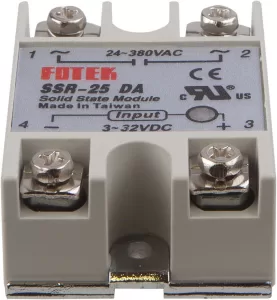
Conclusion
To sum up, a solid-state relay (SSR) is an electronic device that can replace mechanical relays by using semiconductor components. SSRs have no moving parts, which means they offer several advantages such as faster switching speeds, longer electrical life, reduced noise generation, and lower contact resistance. Depending on the application and load requirements, SSRs use thyristors (SCRs), triacs, or power MOSFETs as the switching devices. They are widely used in various industries such as automotive, industrial automation, robotics, and power electronics. SSRs are compact in size, compatible with AC and DC loads, and have reliable performance, making them a popular choice for controlling and switching electrical loads in modern electronic systems.Populer Posts
5SGSED6K3F40I3LG
Intel
LFSC3GA40E-5FFN1152I
Lattice Semiconductor Corporation
1SG250HN3F43I1VG
Intel
XC2V1000-4BG575I
AMD
ICE65L01F-LCB132I
Silicon Blue
1SG250HN3F43I2LG
Intel
5SGXEA7K3F40C2LG
Intel
EP2C35U484C7
Intel
5SGXMA5K2F40I3LG
Intel
EP4SGX360FH29C3G
Intel
XCV1000E-6BG560C
AMD