


NPN vs PNP Transistor: What is the difference between them?
September 19 2023  1426
1426
1426Inquiry
Global electronic component supplier AMPHEO PTY LTD: Rich inventory for one-stop shopping. Inquire easily, and receive fast, customized solutions and quotes.
QUICK RFQ
ADD TO RFQ LIST
In this blog, we will compare the two main types of transistors: NPN and PNP. We will explain what they are, how they work, and the key differences between them. We will also discuss some of the applications of NPN and PNP transistors.
What is a transistor?
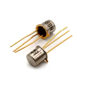
A transistor is a three-terminal electronic component that can be used to control the flow of electricity. It was the first electronic component to have the ability to switch or amplify an electric current. Although there are other types of transistors, bipolar junction transistors are still commonly employed in digital circuits because they are a straightforward technology that may be utilized to build sophisticated electronic circuits. One of the greatest discoveries of the 20th century was the transistor. From computers and cellphones to cars and airplanes, they are found in almost every electrical gadget. In order to create the intricate electronic circuits that run our contemporary world, transistors—which are tiny switches that regulate the flow of electricity—are necessary.What are the two basic types of transistors?
Bipolar junction transistors (BJTs) The base, emitter, and collector are the three semiconductor layers that make up a BJT. Electrons are emitted by the emitter, are controlled by the base in their movement between the emitter and collector, and are then collected by the collector. To control the movement of a larger current from the emitter to the collector, BJTs use a tiny base current. Current amplification is what is occurring here. BJTs are a common component in many different types of electronic devices, such as computers, smartphones, and televisions.- NPN bipolar junction transistor
- PNP bipolar junction transistor
Who invented the transistor?
John Bardeen, Walter Brattain, and William Shockley of Bell Labs created the transistor in 1947. Their innovation transformed the electronics sector and laid the way for creating contemporary computers and other electronic devices.What does a transistor do?
A transistor is a semiconductor device that has the ability to switch or amplify electronic signals. It is made up of a collector, a base, and an emitter, three doped semiconductor layers. A little voltage provided to a transistor's base allows a significantly bigger current to flow from the collector to the emitter. Transistors are extremely beneficial in electrical circuits due to their amplification effect.How does a transistor work?
A tiny current at the base of a transistor controls the amount of current that flows between the emitter and collector. The transistor is off when there is no current at the base and no current passes from the emitter to the collector. The transistor is turned on and current can flow from the emitter to the collector when a modest current is applied to the base. It follows that the amount of current flowing from the base to the emitter is proportionate to the amount flowing from the collector to the emitter. As a result, a modest base current can regulate a much greater collector current. For signal amplification, transistors are extremely helpful for this reason. Switches can also be created using transistors. No current flows from the emitter to the collector when the base current is switched off, which also turns off the transistor. Current travels from the emitter to the collector when the transistor is activated by the base current. Because they can represent the binary numbers 0 and 1, transistors are perfect for use in digital circuitry.How to test a transistor?
- Identify the transistor pins: The emitter, base, and collector pins of a transistor are the three pins that it generally has. Use a multimeter in diode mode to locate these pins or see the transistor datasheet. Typically, the base and collector are connected to the smaller pins, with the emitter being attached to the largest pin.
- Set up the multimeter: If available, switch your multimeter to the hFE (current gain) or diode test modes. Make sure the positive lead of the multimeter is connected to the anode and the negative lead to the cathode when utilizing the diode test mode.
- Test the base-emitter junction: Placing the multimeter probes over the transistor's base-emitter junction will allow you to test the base-emitter junction. The positive lead of the multimeter should be linked to the base of an NPN transistor, and the negative lead should be connected to the emitter. The connections are the opposite in a PNP transistor. If the junction is working properly, the multimeter should show a voltage drop of approximately 0.6 to 0.7 volts. The junction could be defective if the voltage drop differs noticeably from what is expected or if there is no voltage drop.
- Test the base-collector junction: The base-collector connection should be tested by repeating the procedure. The base of an NPN transistor should be linked to the positive lead of the multimeter, and the collector should be connected to the negative lead. Reversed connections are used in PNP transistors. If the junction is operating properly, the multimeter should show a voltage drop similar to the base-emitter junction (between 0.6 and 0.7 volts). The junction could be defective if there is no voltage drop or a voltage drop that is significantly different.
- Test the hFE (current gain): If your multimeter has a transistor hFE test mode, you may use it to determine the current gain of the transistor. This is known as testing the hFE (current gain). To do this test, adhere to the instructions that came with your multimeter. The hFE value of a healthy transistor should fall within the parameters listed in the datasheet.
- Additional tests: You can run more complex tests to evaluate the performance of the transistor if you have access to an oscilloscope or a transistor tester, including measuring the gain-bandwidth product or looking for leakage currents.
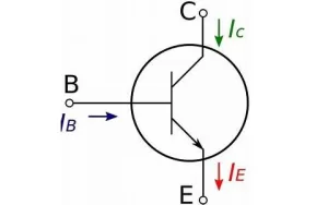
NPN transistors
NPN transistor symbol
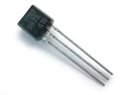
PNP transistors
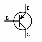
PNP transistor symbol
Video related to NPN and PNP Transistors
Differences between NPN and PNP transistors
One of the main differences between these two transistors is that when a positive supply is given to the base terminal of the NPN transistor, the flow of current will be between the collector and emitter terminals. When a negative supply is given to the base terminal of a PNP transistor, the charge carrier supplies move from the emitter terminal to the collector. In tabular form, many parameters are used to discriminate between NPN and PNP transistors. The key differences between NPN and PNP transistors are the following:- The NPN and PNP transistor symbols are nearly identical; the main distinction is the arrow's direction, which is based on the emitter. The arrow goes inside in a PNP transistor and moves outward to the base in an NPN transistor.
- The PNP transistor is activated when holes enter the base, whereas the NPN transistor is activated when electrons enter the base.
- The inside current in NPN transistors is caused by the shifting positions of the electrons, whereas the inside current in PNP transistors is caused by the shifting positions of the holes.
- The output current in NPN transistors is created by the flow of holes, whereas in PNP it is created by the flow of electrons.
- For NPN transistors, the minority charge carrier is a hole, while for PNP transistors, it is an electron.
- Because an electron serves as the main charge carrier in an NPN transistor, its switching time is longer than that of a PNP transistor.
- Both the NPN and PNP transistors have a connection that is forward-biased at the emitter-base junction.
- The NPN and PNP transistors' collector-base junctions are reverse-biasedly linked.
Applications of NPN and PNP transistors
NPN and PNP transistors are used in a wide variety of electronic applications. Some common examples include:- Amplifiers
- Switches
- Logic gates
- Power supplies
- Motor controllers
- Sensors
Applications of NPN transistor
- Primarily used for switching reasons.
- They are utilized in a Darlington pair setup to amplify weak signals.
- In circuits where we must drain the current.
- Additionally, they are utilized in temperature sensor circuits.
- They can function effectively in situations requiring very high frequencies.
- Used in logarithmic converters.
Applications of PNP transistor
- They are mostly used as switches.
- In amplification circuits, they are employed.
- They are used in multi-transistor circuits called Darlington pair circuits.
- They are now also utilized in robotics.
- Electric motor current flow is managed using PNP transistors.
- PNP transistors are used in matched pair circuits to generate the required and simultaneous power.
Can NPN be used instead of PNP?
Yes, NPN transistors can be used in place of PNP transistors in some situations, but there are a few crucial things to bear in mind. These are the specifics:- Polarity: The polarity of the current flow distinguishes NPN and PNP transistors from one another. The current in an NPN transistor travels from the emitter to the base, and then to the collector. In a PNP transistor, the current travels from the emitter to the base before turning around and going to the collector. This indicates that the current polarities in the two different types of transistors are switched around.
- Voltage Levels: Because of their differing polarities, NPN and PNP transistors require distinct voltage levels. When compared to the emitter, the base of an NPN transistor normally needs to be positive, whereas the base of a PNP transistor typically needs to be negative. As a result, the voltage levels and polarities of the circuit must be changed when an NPN transistor is used in place of a PNP transistor.
- Circuit Modifications: If a PNP transistor is replaced with an NPN transistor, the circuit may need to be altered. To satisfy the NPN transistor's various polarities and voltage requirements, for instance, the biasing resistors and voltage sources may need to be reorganized or modified.
- Current and Power Ratings: It's critical to confirm that the NPN transistor used as a stand-in can manage the circuit's necessary current and power levels. Verify the NPN transistor's maximum ratings on its datasheet and compare them to the specifications of the circuit.
Conclusion
NPN and PNP transistors are two of the most important types of transistors. They are used in virtually every electronic device, from computers and smartphones to cars and airplanes. NPN transistors are more common than PNP transistors, but both types are essential for building the complex electronic circuits that power our modern world.Populer Posts
AGL400V5-CS196
Microchip Technology
1SG211HN2F43E2VG
Intel
XCS30-3BG256C
AMD
EP3CLS150F780C8
Intel
EP1K50XXB
Intel
EP2AGX125EF29I3N
Intel
5SGXMA5K1F40C1G
Intel
M1AFS1500-FG676
Microchip Technology
5SGXEB5R2F43I3L
Intel
A54SX08-1TQ144
Microsemi Corporation