


Flip-Flop vs. Latches: Main differences between them
August 21 2023  1833
1833
1833Inquiry
Global electronic component supplier AMPHEO PTY LTD: Rich inventory for one-stop shopping. Inquire easily, and receive fast, customized solutions and quotes.
QUICK RFQ
ADD TO RFQ LIST
Flip-Flop is synchronous, but Latches is asynchronous. Flip-flops are edge sensitive, but Latches are extremely sensitive and use an enable signal.
What is flip-flop?
A flip-flop is a fundamental digital storage circuit that can hold one piece of data. A timing circuit uses a flip-flop as a storage component. A flip-flop, combination circuit, or both timing circuits are used to produce the output. When the clock pulse is in the active state, the flip-flop's state is altered; when it is in the inactive state, it is unaffected. Particularly, synchronous timing circuits employ non-clocked flip-flops as storage elements while asynchronous timing circuits use clocked flip-flops as storage components.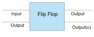
What is Latch?
An object used to store one bit of data is called a latch. Although they appear similar to flip-flops, these are not synchronous devices. They don't operate on the clock's outer edges like FFs do. A latch is a piece of equipment with two stable states: high output and low output. The latch can immediately alter the data stored after it has been declared activated. The enable signal constantly checks the input after it is activated. These circuits can operate in two states, high and low, depending on the enabled signal.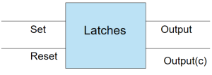
Types of Latches
- SR Latch
- Gated SR Latch
- D latch
- Gated D Latch
- JK Latch
- T Latch
|
SR Latch |
|
|
|
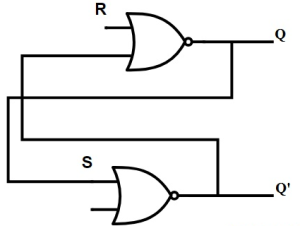
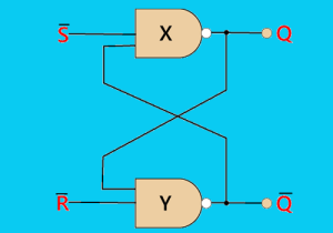
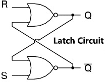
An asynchronous device known as an SR (Set/Reset) latch operates independently for control signals by relying on the S-state & R-inputs. The two inputs are exchanged as well as canceled when these latches are constructed using NAND gates. Therefore, it is known as SR'-latch. |
|
Gated SR Latch |
|
|
|
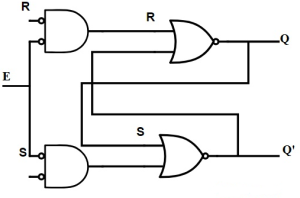
A gated SR latch is all that an uncomplicated extension of the SR latch is. Prior to the information being latched, it provides an enable line that needs to be driven high. The output may change even in the middle input of the enable pulse, despite the fact that the control line is necessary, therefore the latch is not synchronous. |
|
D latch |
|
|
|
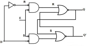
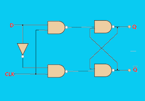
An electronic latch can be used to store a single piece of data. When the clock input is high, the D latch is used to "latch" or capture the logic level that is present on the Data line. When the clock pulse is high and the data on the D line changes state, the output, Q, follows the input, D. |
|
Gated D Latch |
|
|
|
The gated D latch is designed to change only the gated SR latch, and the only change to the gated SR latch is that input R must be modified to invert S. |
|
JK Latch |
|
|
|
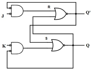
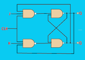
The RS latch and the JK latch are comparable. As seen in the diagram, this latch has two inputs: J and K. This form of latch eliminates the confusing status at this point. The output will be switched when the JK latch input is high. The output feedback to the input, which is absent in the RS latch, is the sole distinction that can be made. |
|
T Latch |
|
|
|
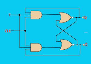
As long as the JK Latch input is shorted, a T Latch can form. The T Latch will operate in this manner when the input of the latch is high, and the output will then be switched. |
Types of Flip Flop
- SR Flip Flop
- J-K Flip Flop
- D Flip Flop
- T Flip Flop
| SR Flip Flop | |
|
|
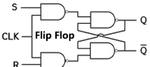
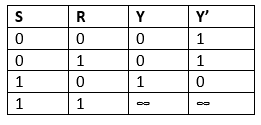
The most common type of flip-flop found in digital systems is the S-R flip-flop. In an SR flip flop, the output Y will be high, and Y' will be low if the set input "S" is true. Maintaining the circuit's wiring is important once the outputs have been constructed. We maintain the wiring up until the set or reset input is high or the power is switched off. |
|
J-K Flip Flop |
|
|
|
The S-R flip-flop's drawback of having undefinable states is overcome by the JK flip-flop. The JK flip-flop is made by altering the SR flip-flop. By improving the S-R flip flop, the J-K flip flop is made possible. When both S and R inputs are set to true, the SR flip-flop makes a mistake. However, the JK flip-flop yields the intended outcomes. |
|
D Flip Flop |
|
|
|
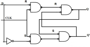
The D-type Flip-flop addresses one of the main problems with the primary SR NAND Gate circuit, namely the fact that it disallows the input circumstances of SET = "0" and RESET = "0." This state overrides the feedback latching operation, forcing both outputs to logic "1," and the input that reaches logic level "1" first loses control while the input that is still at logic "0" controls the latch's final state. |
|
T Flip Flop |
|
|
|
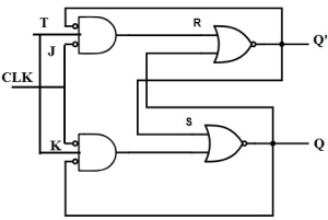
The T flip-flop is used, the same as the JK flip-flop. Unlike JK flip flops, T flip flops only have one clock input. The T flip flop is produced by merging both of the JK flip flop's inputs together into a single piece of information. The T flip-flop is also known as a toggle flip-flop. These T flip-flops may find the complement of its condition. |
Pros and cons of Flip-Flop and Latches
Pros and cons of Latches| Pros of Latches: |
| The latch's shape is quite compact and takes up less space. |
| Latch-based circuits use borrowed time to finish operations if they don't finish in a predetermined amount of time. |
| Comparing latches to flip-flop circuits, aggressive clocking is provided by latches. |
| When compared to flip-flops, the latch design is far more versatile. |
| Latching devices use less energy. |
| Because they are designed to be asynchronous and do not require a CLK signal, latch performance in high-speed circuits is rapid. |
| Cons of Latches: |
| Level sensitivity makes analysis of the circuit challenging. |
| A second CAD application can be used to test the circuit. |
| These are less likely because there is a likelihood they will have an impact on the race condition. |
| There is a potential for meta-stability when a latch is level sensitive. |
Pros and cons of Flip Flop
| Pros of Flip Flop: |
| Utilizing shielding and filtering to lower the amount of noise in a system is crucial to preventing this. |
| A flip-flop can randomly switch states if a system is subjected to too much noise, which can lead to system failure. |
| Flip-flops have a number of drawbacks, one of which is their susceptibility to noise. |
| Cons of Flip Flop: |
| Flip-flops can be used to create intricate waveforms and can also deliver timing signals. |
| In order to control the flow of data in a system, flip-flops can also be used to store data in a system's registers. |
| Flip-flops have the major benefit of being able to save data even when the power is off. They can thus be used to store data in memory. |
Flip-Flop vs. Latches Applications
Flip-Flop Applications
- The flip-flop circuit is mostly used in memory.
- Bounce elimination switches
- Registers
- Counters
- Frequency division
- Data storage and transport
Latches Applications
- Circuits like power gating and clocks use latches as a storage mechanism.
- D latches can be used with input or output ports, which are asynchronous systems.
- In synchronous two-phase systems, data latches are employed to lower the transit count.
- Latches are typically employed to maintain the conditions of the bits utilized to encode binary numbers.
- Latches are single-bit components frequently utilized in data storage and computation.
Flip-Flop vs. Latches circuit and truth table
|
Flip-Flop Circuit |
Flip-Flop truth table |
|
|
|
|
Latches circuit |
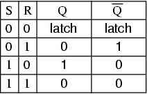
Latches truth table |
|
|
|
Flip-Flop vs. Latches
|
Latches |
Flip-Flop |
| At the clock domain crossings in the scan chain, DFT requires latches as a lockup state to prevent erratic behavior. | Use scannable flops in DFT (controllable and observable). |
| Increasing the amount of manual calculations and tool control necessary to guarantee time is met. | Checking design timing is simple when static timing analysis (STA) tools are used. |
| Cycle-borrowing, assuming that each loop runs for a complete cycle, increases the setup time for the following register step. Timing mismatch is taken into account by designers, who consider latches as a possible solution. | It launches on one rising edge, thus data must be set up before the next rising edge. If it's late, the system collapses. Even if it arrives early, time is squandered because of Flops' jagged edges. |
| The highly sensitive latches depend on an enable signal to function. | Flip-flops are edge sensitive. |
| For ASICs with severe clock skew, latching significantly reduces the clock period. | Since they are not transparent, even for high-speed pulsed flip-flops with zero setup time, the effect of the clock skew is not lessened. |
| Sequential circuit building blocks known as latches can be made using logic gates. | Flip-flops are a common building element in sequential circuits, although latches can also be used to make flip-flops. |
| The latch is an asynchronous block. Therefore, it is important to ensure that the combinational functions that supply the input signals to the latch are race-free. Otherwise, they might generate mistakes that could latch and put your system in danger. | Flip-flops, on the other hand, only experience state changes when a control signal goes from high to low or from low to high. |
| The level of the latch, which is a binary input of either 1 or 0, affects both the output of the current state and the input of the following state. | When the clock pulse, which can be either positive (+ve) or negative (-ve), changes, the next state input and output of a flip-flop also change. |
Conclusion of Flip-Flop vs. Latches
Flip-Flop is synchronous, but Latches is asynchronous. Flip-flops are edge sensitive, but Latches are extremely sensitive and use an enable signal. A latch and a flip-flop further vary in that a latch can change its state whenever its inputs change, whereas a flip-flop can only do so when a control signal changes from high to low or from low to high. A latch is level-triggered, whereas a flip-flop is edge-triggered. Latch considerations must be a constant part of your design.Populer Posts
M2GL090-FG484I
Microchip Technology
5SGXEABK1H40I2G
Intel
10AX066K2F35I2LG
Intel
5CEFA7F23C6N
Intel
MPF200T-FCVG484E
Microchip Technology
5SGXEA7N2F45C2LG
Intel
5SGXEA7H2F35I3G
Intel
ICE40LP8K-CM225
Lattice Semiconductor Corporation
EP4SGX290NF45C4N
Intel
5SGXEB5R2F43I2G
Intel
EP4CE6E22C9LN
Intel