


Beginner's Guide to the Rectifier Circuit
August 25 2023  1042
1042
1042Inquiry
Global electronic component supplier AMPHEO PTY LTD: Rich inventory for one-stop shopping. Inquire easily, and receive fast, customized solutions and quotes.
QUICK RFQ
ADD TO RFQ LIST
If you're new to electronics or looking to understand how rectifiers work, you've come to the right place. In this comprehensive blog, we'll cover all the essentials, from the basics of rectification to different types of rectifier circuits. Get ready to dive into the world of rectifiers and gain a solid understanding of their features. Let's get started!
What is A Rectifier Circuit?
A rectifier circuit is an electronic circuit that converts alternating current (AC) to direct current (DC). The primary function of a rectifier circuit is to convert the alternating voltage and current into a unidirectional flow. The rectifier circuit is commonly used in various electronic devices and power supplies where DC power is required. It is particularly useful in applications such as power supplies, battery chargers, motor drives, and audio amplifiers.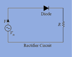
Types of Rectifier Circuit
There are several types of rectifier circuits used to convert alternating current (AC) to direct current (DC). The choice of rectifier circuit depends on factors such as the desired output waveform, efficiency, and cost. Here are the most common types of rectifier circuits:Half-Wave Rectifier
The half-wave rectifier is the simplest type of rectifier circuit. It uses a single diode to conduct current in only one direction during the positive half-cycle of the input AC voltage. The negative half-cycle is blocked, resulting in a pulsating DC output waveform. The half-wave rectifier is relatively simple and inexpensive but has lower efficiency and higher ripple compared to other rectifiers.Full-Wave Rectifier
The full-wave rectifier is more efficient than the half-wave rectifier as it utilizes both halves of the input AC waveform. There are two types of full-wave rectifiers: center-tapped and bridge rectifiers.- Center-Tapped Full-Wave Rectifier: This type of rectifier uses a center-tapped transformer and two diodes. The center-tapped secondary winding of the transformer splits the input AC voltage into two halves. Each diode conducts during one half-cycle of the input voltage, resulting in an output waveform that combines both halves of the input waveform. The center-tapped full-wave rectifier has a higher efficiency than the half-wave rectifier but still has some ripple.
- Bridge Rectifier: The bridge rectifier is the most commonly used type of rectifier circuit. It consists of four diodes arranged in a bridge configuration. Unlike the center-tapped rectifier, it does not require a center-tapped transformer. The bridge rectifier conducts current in both halves of the input waveform and combines them to produce a smoother DC output waveform. It has higher efficiency and lower ripple compared to the center-tapped and half-wave rectifiers.
Bridgeless Rectifier
The bridgeless rectifier is an advanced rectifier circuit that aims to further improve efficiency and reduce losses. It eliminates the need for diodes in series with the load, reducing voltage drops and power losses. Bridgeless rectifiers use additional semiconductor devices, such as MOSFETs or IGBTs, to achieve rectification without the traditional diode bridge. This type of rectifier is commonly used in high-power applications.How Rectifier Circuit Works?
By using diodes, a rectifier circuit converts AC (alternating current) to DC (direct current). Diodes are electronic devices that permit current to flow in a single direction only. In a rectifier circuit, the diodes are positioned in a particular arrangement to rectify the AC voltage or current. Different types of rectifier circuits work in different ways. Now let’s take a close eye on them. Half-Wave Rectifier: In a half-wave rectifier circuit, a single diode is used. During the positive half-cycle of the AC input voltage, the diode conducts and allows current to flow through it, resulting in a positive half-cycle of the output waveform. However, during the negative half-cycle, the diode blocks the current, resulting in no output. As a result, the output waveform of a half-wave rectifier is a pulsating DC waveform with only half of the input waveform. Full-Wave Rectifier: A full-wave rectifier circuit can be implemented using either two diodes or a bridge rectifier configuration. Let's consider the bridge rectifier configuration for simplicity. The bridge rectifier consists of four diodes arranged in a bridge arrangement. During the positive half-cycle of the AC input voltage, two diodes conduct and allow current to flow through them, resulting in a positive half-cycle of the output waveform. During the negative half-cycle, the other two diodes conduct and allow current to flow in the opposite direction, still resulting in a positive half-cycle of the output waveform. As a result, the output waveform of a full-wave rectifier is a smoother pulsating DC waveform compared to a half-wave rectifier. In both half-wave and full-wave rectifiers, the output waveform is a pulsating DC waveform. To further smoothen the output waveform and reduce the ripple, a filter capacitor is often added after the rectifier circuit. The capacitor helps to store charge during the peaks of the pulsating waveform and release it during the troughs, resulting in a smoother DC output.Rectifier Circuit with Capacitor
A rectifier circuit with a capacitor is commonly referred to as a "rectifier with a smoothing capacitor" or a "capacitor-input rectifier." It is a configuration that combines a rectifier diode or diode bridge with a capacitor to convert AC voltage into a smoother DC voltage. The addition of a capacitor in the rectifier circuit helps reduce the ripple voltage, which is the residual AC component that remains in the rectified DC output. The capacitor acts as a filter, smoothing out the pulsating DC waveform by storing electrical charge during the peaks of the rectified voltage and releasing it during the troughs, effectively filling in the gaps between the voltage peaks.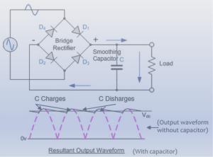
Rectifier Circuit without Transformer
A rectifier circuit without a transformer is commonly known as a "capacitor-input rectifier" or a "capacitor-input filter." It is a configuration that uses diodes and capacitors to convert AC voltage into DC voltage without the use of a transformer.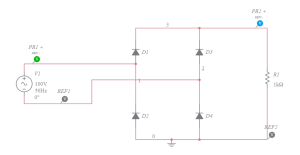
Why Use Rectifier Circuit?
Using a rectifier circuit is beneficial for several reasons: Conversion of AC to DC: The main advantage of using a rectifier circuit is its ability to convert alternating current (AC) to direct current (DC). Many electronic devices and electrical systems require DC power to function properly. By rectifying the AC voltage, the rectifier circuit ensures a continuous and unidirectional flow of current, which is essential for the operation of various electronic components. Power Supply Stability: DC power is more stable and consistent compared to AC power. Rectifier circuits provide a steady flow of DC power, eliminating the fluctuations and changes in direction that occur in AC power. This stability is crucial for sensitive electronic devices that require a constant and reliable power source. Compatibility with Electronic Components: Many electronic components, such as transistors, integrated circuits, and microcontrollers, operate on DC power. By using a rectifier circuit to convert AC power to DC power, these components can be powered and function properly. Rectifier circuits ensure that the voltage and current supplied to the components are within their required ranges, preventing damage and ensuring optimal performance. Efficient Power Conversion: Rectifier circuits can achieve high levels of efficiency in converting AC power to DC power. Advanced rectifier designs, such as bridge rectifiers, have improved efficiency and reduced power losses compared to simpler rectifier configurations. This efficiency is important for reducing energy waste and optimizing the overall performance of electrical systems. Compatibility with Power Sources: Rectifier circuits allow the use of different power sources, including the main power grid, generators, and renewable energy systems. AC power from these sources can be easily rectified to provide the required DC power for various applications. This flexibility in power source compatibility makes rectifier circuits versatile and adaptable to different environments and energy systems. Application in Various Industries: Rectifier circuits find widespread application in numerous industries, including electronics, telecommunications, automotive, aerospace, and renewable energy. They are used in power supplies, battery charging systems, motor drives, lighting systems, and many other electrical devices and systems. In summary, using a rectifier circuit provides the necessary conversion from AC to DC power, ensuring compatibility with electronic components, stability in power supply, efficiency in power conversion, and compatibility with various power sources. These advantages make rectifier circuits essential components in modern electronic devices and electrical systems.Conclusion
Congratulations! You've reached the end of our beginner's guide to rectifier circuits. We hope this comprehensive blog has provided you with a solid foundation in understanding rectification and various types of rectifier circuits. Armed with this knowledge, you can now explore and experiment with rectifiers in your electronic projects. Remember, rectifiers play a crucial role in converting AC to DC, opening up a world of possibilities in electronics.Populer Posts
AX125-FG324
Microsemi Corporation
5SGXEA5K3F40I3LG
Intel
AX1000-BGG729I
Microchip Technology
OR2T12A4BA352-DB
Lattice Semiconductor Corporation
5AGXFB3H4F35I3G
Intel
EP4CGX22BF14C7
Intel
5SGXEA4K3F40I3LG
Intel
5SGXEA5H3F35I3N
Intel
A1020B-2VQG80I
Microsemi Corporation
5SGXEB6R2F43I2LG
Intel
EP3SE50F484C3G
Intel